Disclosure: This page contains affiliate links. As an Amazon Associate, Yard Foundry earns from qualifying purchases.
A good robotic lawn mower installation starts with a property survey, not the app. Locate the charging station first, map every connected lawn area, record slopes and narrow passages, then confirm whether the chosen mower uses a physical loop or virtual boundaries. Stake a boundary wire on the surface before burying it. For a wire free system, prove satellite and network coverage across the whole work area before drawing the final map.
This is a research based installation guide. Yard Foundry has not installed or physically tested the mower systems discussed here. Exact clearances, wire offsets, slope limits, and mapping steps come from the manual for the model being installed.
Choose the installation architecture before opening the box
A boundary wire mower follows a low-voltage loop around the work area. Many wired models also use one or more guide wires to find the charger or reach remote sections. A wire free mower stores virtual work areas, exclusion zones, and transport paths. Depending on the model, it may use satellite correction from a local reference station, a cloud service, cameras, or a combination of sensors.
Physical wire demands more labor at the start but does not rely on a virtual boundary signal at every edge. Virtual boundaries are easier to edit, but a product that depends on satellite positioning needs an adequate view of the sky. Buildings, dense canopy, tall hedges, and narrow side yards can create difficult pockets. Test the exact system rather than assuming that a phone’s GPS or cellular signal predicts mower performance.
The mower’s published area rating is only one fit check. Measure the steepest route with the Robot Mower Slope Calculator, then compare that grade with the manual’s limit for mowing, boundaries, and the charging-station approach. Those limits may differ.
Walk the property and draw the first map
Sketch the lawn as connected shapes. Mark beds, trees, ponds, retaining walls, steps, playground equipment, exposed roots, gravel, public sidewalks, and driveways. Record the width of every passage at mower height. A gap that looks generous while standing may leave little room once the model’s boundary offsets are applied on both sides.
Separate fixed obstacles from seasonal ones. A mature tree is permanent. A trampoline, temporary pool, or new bed may be better handled with an exclusion zone that can change. Also identify disconnected lawns. Some systems let one mower manage separate work areas, but the mower may need to be carried between them if no safe route exists.
Before driving stakes or burying cable, follow the local utility-location process. Husqvarna’s current U.S. wired installation checklist tells owners to have underground utilities located through the municipal 811 service. The boundary wire is shallow, but staples, edging tools, and trenching equipment can still meet an existing service.
Place the charging station first
The station needs a firm, level surface with drainage, nearby outdoor power, and a clear approach. Avoid a hollow that collects water or a flexible deck section that bends the base. Confirm cable reach without stretching an extension arrangement that the manufacturer does not allow.
Approach clearance is model specific. Husqvarna’s charging-station placement guide, for example, gives different free-space requirements for its physical wire and EPOS installations. It also says not to secure the station permanently until the wires have been installed and the setup works. Treat those dimensions as an example for that product family, not a universal rule.
A wired station should not sit beside coils of excess loop wire, steel edging, or other metal that can disturb its signal. A satellite based station or docking point may need clear sky. Some cloud assisted models also need reliable Wi-Fi or mobile coverage for navigation, updates, or both. Read the offline behavior before choosing a spot hidden behind a building.
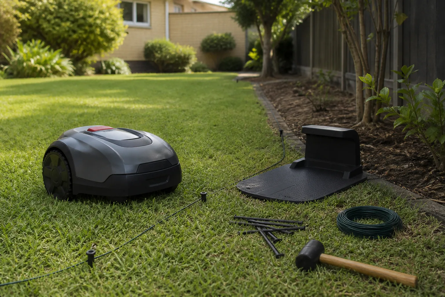
Robotic lawn mower installation with boundary wire
Lay the loop on the surface
Mow the grass and clear debris before installation. Starting at the station, follow the model’s required setback from hard paving, flower beds, walls, drops, water, and public areas. These distances change with edge type and mower design, so copying a neighbor’s measurement is risky.
Use smooth bends rather than sharp corners. Leave service slack at planned junctions and future repair points. Where the lawn may change, surface staking makes adjustment far easier than immediate burial. Grass usually grows around a properly pinned wire, and the loop can be buried later after a stable test period.
Create islands and safe crossings
Run the loop out to a fixed object, around it, and back along the same route only where the manual permits the outgoing and returning wires to lie together. Protect water edges, steep drops, and places where a navigation error would cause damage with the setback or physical barrier required by the manufacturer.
A driveway crossing needs a protected route that will not be cut by vehicle traffic or future resurfacing. Record the path on a simple property map before it disappears under turf. That sketch saves time when an edger, aerator, or planting project is planned later.
Add guide wires where the mower needs help
Guide wires can shorten the search for the dock and help a wired mower reach remote lawn sections. Husqvarna’s current guide wire instructions recommend a guide through narrow passages and require a test that confirms the mower can follow it and dock. Other brands route and name guidance differently, so use the supplied manual.
Keep the guide clear of sharp angles, route it across slopes in the allowed direction, and avoid crossing the boundary loop. Mark every connector at the station. A small label makes winter removal and spring setup less error prone.
Connect, pair, and test before burial
Use the approved waterproof connectors rather than twisting bare wire together. Once the loop and guides are connected, check the station indicator, pair the mower, and run a complete test. Watch it leave the dock, follow each passage, turn at every boundary type, reach remote areas, and dock on the first attempt.
Husqvarna provides a dedicated docking test procedure for its wired models. The larger lesson applies broadly: do not bury the route until the mower has proved it can return without repeated retries. Adjust first, then secure the final path.
Compare robotic mower boundary wire installation kits on Amazon (paid link). Confirm wire type, connector compatibility, and total length against the exact mower manual.
Wire free robotic mower setup
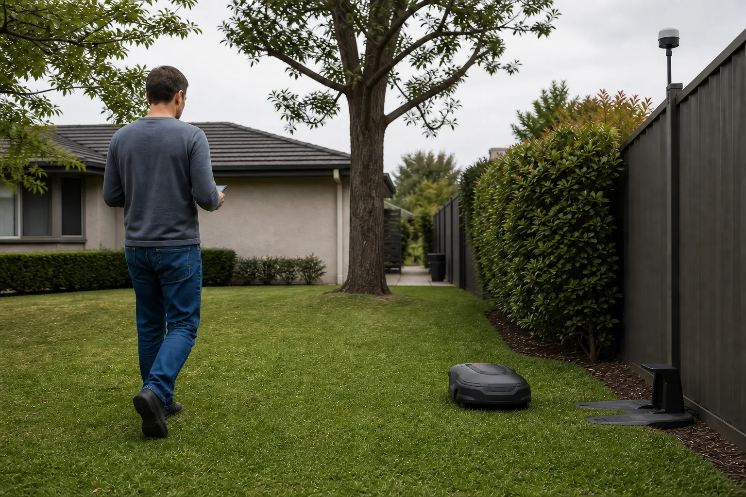
Prove positioning and connectivity
Update the mower and app, then establish the positioning service before drawing boundaries. For Husqvarna EPOS, the current U.S. installation guide says the mower and reference station need a clear sky view, while cloud operation is available only in supported locations and may require stable Wi-Fi or mobile coverage. Other systems have their own antennas, beacons, cameras, and coverage rules.
Walk beneath the tree canopy, along the house wall, and through each passage while the system reports positioning quality. A good signal at the charger does not prove the far corner will work. If the model allows a reference station, install it on a rigid support in the specified location. Moving it later may force the map to be recreated.
Map work areas and exclusion zones
Use the app’s guided drive or mapping process to trace the lawn edge at the specified offset. Slow down at corners and record extra points around curves only as directed. Create separate work areas where different cutting heights or schedules are needed. Draw exclusion zones around beds, young trees, water, and temporary projects.
Then create any transport path between the dock and work area. The mower may follow a different accuracy rule on transport paths than while cutting, so test clearances in both directions. Do not assume a map line shown over aerial imagery is precise enough. Observe the mower at ground level.
Run edge and obstruction tests
Test the mapped boundary in dry daylight with the yard clear. Watch wheel placement beside drops, curbs, mulch, gravel, and water. Check under each tree and beside every tall structure. If the mower pauses or loses position repeatedly, change the route, improve the reference setup, or use a supported physical barrier or hybrid boundary where the model allows it.
Commission the mower over a full week
Start at a higher cutting setting rather than asking the small blades to remove an overgrown layer. Clear sticks, toys, hoses, fruit, and loose wire before every early run. Watch the first complete cycle instead of sending the mower out overnight.
For the next several days, inspect:
- Docking on the first attempt
- Wheel marks near the charger and in narrow corridors
- Uncut pockets behind obstacles
- Stops beneath trees or beside buildings
- Contact with edging, roots, gravel, or garden furniture
- Whether the schedule keeps pace without running through unsuitable conditions
Change one setting at a time. If a passage fails, first determine whether the cause is physical clearance, traction, wire geometry, or positioning. Redrawing the whole map can hide the original problem.
Common setup symptoms
| Symptom | Likely installation check |
|---|---|
| Mower retries docking | Station level, approach clearance, guide path, docking point, and signal interference |
| Uncut remote area | Guide wire or transport path, passage width, work-area assignment, and schedule |
| Stops near trees or walls | Satellite view, reference or cloud connection, and supported fallback behavior |
| Crosses or misses an edge | Exact wire setback, loose staples, virtual map offset, and wheel slip |
| Wire break after lawn work | Mapped cable route, connectors, recent edging, aeration, or digging |
When professional installation earns its cost
Professional help is reasonable for large irregular lawns, many islands, hard-surface crossings, steep transitions, uncertain satellite coverage, or a reference station that needs elevated mounting. It also makes sense when outdoor power must be added. Ask whether the quote includes mapping, guide wires, obstacle zones, a docking test, owner training, and a follow-up visit.
Compare the full first-year cost with the Robot Mower Ownership Cost Calculator. Include the installation kit, reference hardware, mounting, extra charger, professional labor, replacement blades, and any connectivity fee. The purchase price alone understates the difference between two installation types.
Final handoff checklist
- Utility-location process completed before staking or trenching
- Station level, dry, powered, and tested in its final position
- Boundary offsets or virtual map checked against the exact manual
- Passages, slopes, disconnected lawns, and water edges tested
- Every guide wire, transport path, and exclusion zone verified
- Wire route or virtual map saved with installation notes
- PIN, theft settings, updates, and shared access configured
- First week scheduled for observed daytime runs
A successful installation is the one that docks reliably and stays inside the intended work area under the property’s difficult conditions. For the rest of Yard Foundry’s planning aids, use the tools and calculators hub.